


 86 / 100

CONTROLLO
tecnica
86
Settembre 2017
Automazione e Strumentazione
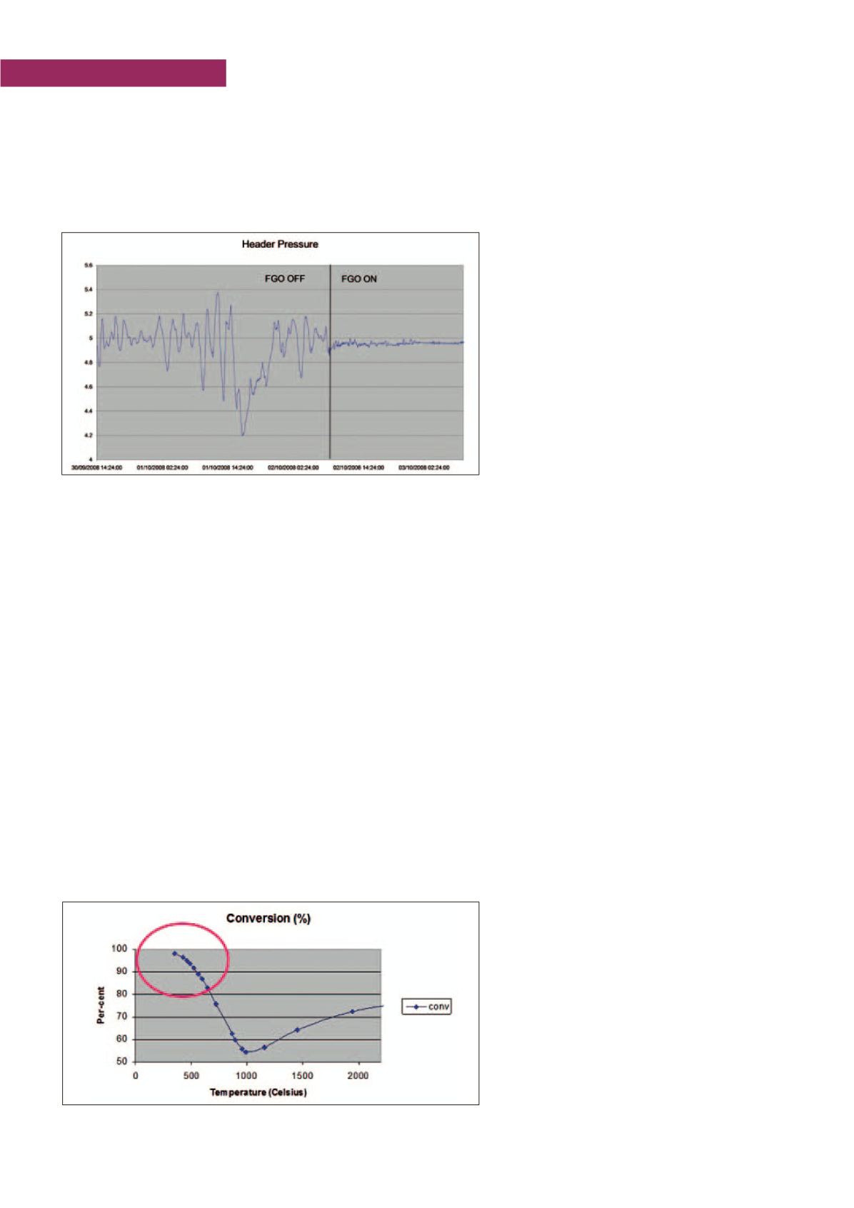
ity’s in the system. In
υ
Figure 3
there is an example of a fuel
gas header pressure control before and after deploying the APC
solution. Benefits audited in this small 90 KBPD refinery were
more than $ 2.1 M per year.
Sulphur Complex Control
Sulphur complex, which is made up of multiple lines and equip-
ment is a very important part of the refinery and must work
properly. Any upsets in the complex, like ammine absorbers/
regenerators, sour water strippers (SWS), sulphur recovery
units (Claus), tail gas treaters (TGT) and incinerators, has a sig-
nificant and costly effect on the overall refinery and on the envi-
ronment. This is where APC applications can provide benefits.
For example, a constrained Claus unit should maximize feed
whenever possible as it permits increasing load to profitable
desulphurization units or even the overall refinery. The unit
should work ‘well’, recovering as much sulphur as possible and
maximizing conversion through a Dew Point Margin minimi-
zation. The unit should also minimize O2 consumption and all
other specific utilities consumptions (fuel, EE, and downstream
TGT unit load).
A key point is the
Dew Point Margin
reduction as this requires
explicit
Dew Point control
. Conversion is limited by reaction
equilibrium. The liquid sulphur forms at dew point in condens-
ers, but if it happens on catalyst it can reduce activity (reduces
conversion), increase pressure drop (increases pressure in
the boiler which is usually one of the major constraints) and
condense Sulphur in catalyst pores (shortens catalyst life and
requires expensive regeneration or rejuvenation procedures).
On the other hand, a Dew Point Margin that’s too high
will reduce conversion, increase energy consumptions
(temperature is too high) as well as increase down-
stream TGT consumptions and loads.
Best in class refiners are able to maintain around a
10-15 °C Dew Point Margin but it is not uncommon
to see sites where the margin is greater than 35 °C.
This is a large margin, paid heavily with reduced con-
version and increased consumptions. Not to mention
the case where a refinery is sulphur limited, causing
a loss in money measured in multiple millions of dol-
lars per year. Building first principle Dew Point infer-
entials permits to address these issues. Not an easy
task since sulphur condenses in catalyst pores and a
capillarity condensation effect occurs. The Dew Point
Limit is a function of many variables, including feed
quality, air flow, air humidity, pressure of the system,
reactor temperatures and more. These variables affect the par-
tial pressure of sulphur in a vapour phase over the catalyst and,
consequently, the related saturation temperature that is already
reduced by the presence of inert gases (N
2
, H
2
O, not reacted
H
2
S, etc.). The accurate first principles Dew Point inferential
can be built, but it requires appropriate competence and integra-
tion of both APC and kinetic modeling technologies.
Achievable benefits can vary significantly depending on the
specific layout and constraints distribution, but benefits are typ-
ically between $ 0.8 and 1.1 million per year for a small 100
KBPD refinery (not considering the case when the refinery is
sulphur limited where benefits can be measured in multi-mil-
lion dollars per year).
Steam Networks Control
A Steam Network can be quite complex with multiple pressure
headers. The major components include steam headers, steam
imports/exports, boilers/HRSGs, gas turbines, steam turbines,
let-down valves and vent valves.
By implementing APC technologies, facilities can experience a
number of benefits. These include:
- Improved steam headers pressure control by manip-
ulating boilers, turbines, and let-downs in order to
stabilize operations and maintain the required steam
production levels;
- Minimized downgrading steam through let-down
valves mainly by manipulating turbine loads, extrac-
tions and, whenever possible, boiler loads;
- Minimized vent flows by manipulating turbine loads
and extractions and, whenever possible/convenient,
boiler loads;
- Control of all constraints, including emission lim-
its during the transition, while optimizing boiler load
changes;
Figure 4 - Claus reactors conversion curve
Figure 3 - Fuel Gas pressure control before and after deploying the APC solution